 |
| August 12, 2014 | Volume 10 Issue 30 |
Designfax weekly eMagazine

Archives
Partners
Manufacturing Center
Product Spotlight
Modern Applications News
Metalworking Ideas For
Today's Job Shops
Tooling and Production
Strategies for large
metalworking plants
Injection-Molding Tips:
Proper planning for parting lines can improve part cosmetics and functionality
By Gus Breiland, Customer Service Engineer Manager, Proto Labs
We're revisiting a popular Design Tip that covers the types of parting lines you may encounter on plastic, metal, and liquid silicone rubber molded parts -- and how you can properly address them.
When you are developing a 3D CAD model to be molded, you may not spend much time thinking about where its parting line will be, but it's worth noting as the location can affect your part in several ways. On some parts, the location for the parting line is obviously right down the middle, while on more complex parts, it may not be as obvious.
Take, for example, a simple plastic cup. The outer face is formed by one mold half (A-Side), while the cup's inner surface and brim will be formed by the other mold half (B-Side). The parting line occurs along the outside edge of the brim of the cup. For other designs, parting lines vary with geometry. A molded yellow flower, which was used as an art piece for children, depicts a parting line along its outer petals (see Figure 1).

Figure 1: A parting line is present along the flower's outer pedals.
When a design is a complex shape, determining where the parting line can be is more complicated. You can assume that if you send an undrafted 3D CAD model of such a part, Proto Labs will determine where the parting line should be. However, in designing such a part, you might want to think about the parting line for one simple reason: Designers and molders look at parts differently. Molders share your interest in producing the best possible part, but the focus is on molding it correctly, whereas designers focus on how it will function after it comes out of the mold. The location of the parting line can affect both.
First of all, the location of the parting line determines the direction of mold opening and, consequently, the direction in which features must be drafted for easy ejection. Second, it affects where any vestiges left by the mating surfaces of the mold halves will be and, potentially, how those vestiges will look. Third, parting-line location can also impact the cost of mold making and the type and cost of secondary operations needed to finish the part.
The plastic toy soldier in Figure 2 is an obvious example of a design with a challenging parting line, but the issue can come up on simpler parts as well.
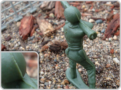
Figure 2: The highlighted "seam" (see inset on lower left) is a result of the parting line (the location where the two halves of the mold meet). A slight mismatch in the mold will leave a raised seam (flash).
For example, a straightforward geometric design with radiused or rounded edges can also be problematic. The parting line has to trace the path along which a tangent to the surface is parallel to the direction of mold opening. In Figure 3, the parting line has been placed across an otherwise smooth surface. Any mismatch in mold edges will create a fairly obvious seam, so a parting line in this location would create a need for tighter tolerances and potentially increase milling costs. The increased likelihood of flash could also impact both the cosmetics and functionality of the part, potentially making assembly of finished parts more difficult.
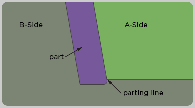
Figure 3: Both mold halves form the parting line, so any mismatch in the mold will leave a seam, changing the shape of the part at the parting line. We recommend placing the parting line on a sharp edge.
If the parting line is instead placed along a sharp edge, the seam would be camouflaged, and the undesired manufacturing, functionality, and cosmetic issues outlined above (see Figure 4) would be avoided.
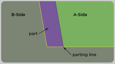
Figure 4: Both mold halves meet to form the sharp edge of the part.
Designing parts for liquid silicone rubber (LSR) molding and metal injection molding (MIM) is similar to thermoplastic molding, though with both of these processes, additional preparation to prevent flash should be considered. LSR flows into the mold as a liquid and will fill into gaps as small as 0.0002 in., which can result in flash. Though parting lines on LSR parts are likely less visible and less intrusive, they are harder to prevent. You should also make sure that parting lines on LSR are not on a sealing surface. MIM parts may flash easier as well, but a good parting line will be less noticeable due to the shrink factor that parts experience during the multi-step MIM process. Simplifying and minimizing parting lines on both LSR and MIM parts will help you get cleaner parts as quickly as possible.
With all injection-molded parts, there are several ways to address parting line challenges. An awareness of the significance of the parting line is a good start. As stated earlier, parting line location is obvious and not a problem on many parts. For more complex parts, you may be able to use tools within some CAD packages to locate and evaluate split lines, or you can just upload a 3D CAD model online and we'll propose a parting line and suggest appropriate draft based on that orientation. Our software may also point out that the part cannot be made in a straight-pull mold and that design changes, side actions, and/or pickouts may be required.
Whether you get your information from a CAD package or from Proto Labs, keep in mind that the suggested parting line may not be your only option. Neither your CAD program nor our design analysis software knows how you intend to use the part. Look carefully at the suggested parting line, and consider whether its location will work both cosmetically and functionally. If not, there may be other options for your existing design, or you may want to change the design to allow a more suitable parting line for your application. If you need assistance, you can always call a Customer Service Engineer to discuss your design at 877-479-3680.
Source: Protomold
Published August 2014
Rate this article
View our terms of use and privacy policy